Vacuum Circuit Breaker: Fundamentals
Table of Contents
What's Vacuum Circuit Breaker? Definition of VCB
The Vacuum Circuit Breaker (VCB) is a switching device capable for operational switching (on-off operations) of individual circuits or electrical equipment in normal or emergency modes with manual or automatic control, made for a medium voltage of over 1 kV based on the principle of quenching an electric arc that occurs when the contacts open in a vacuum gap. <
The development of power engineering and the transition to higher operating voltages required the development of switching technology, especially switches - devices capable of interrupting short-circuit currents. Simply opening the contacts in the air did not solve this problem; new technologies were needed. The range of operating voltages used in the power industry is increasing, and this growth is now supported by the economic benefits of switching to higher transmission voltages.
The first vacuum circuit breakers took the approach of oil circuit breakers and used bulky spring-motor actuators to open contacts. Such drives had a large number of loaded friction units, which significantly reduced their resource and reliability. The early developers of vacuum circuit breakers underestimated the advantage of vacuum in the form of the ability to operate with small gaps, which allowed for more energy efficient actuators.
So, around 1988, the Tavrida Electric company came up with an idea to use an electromagnetic drive coaxial with a movable contact by a vacuum arc quenching chamber. This made it possible to completely get rid of friction-loaded assemblies, radically increase the resource and reliability of the switches, and at the same time reduce their dimensions several times. In addition, the design of such a drive does not require maintenance, which, together with the maintenance-free vacuum interrupter chambers (bottles), makes it possible to manufacture devices that do not require maintenance during the entire service life (30 years).
Vacuum Interrupter Technology in Medium Voltage: Arc Quenching in Vacuum Gap
An electric arc is an independent discharge that occurs when the contacts are opened. When the contacts are opened at an arbitrary moment in time, when the current in the network is not zero, an instantaneous disappearance of the current cannot occur. An arc ignites between the contacts, which allows the current to continue flowing until the electromagnetic energy is equal to zero.
For the existence of an arc, a conducting medium is necessary, and an arc in a vacuum is no exception, the medium in which a vacuum arc burns - a pair of metal electrodes. When the contacts are opened, cathode spots can form on the electrodes. Cathode spots are microscopic arc anchor points, in other words, miniature craters.
Like any arc, the vacuum arc quenching in the vicinity of the current zero. In a vacuum, the extinction of the arc occurs somewhat earlier than zero, since at least one cathode spot is required for the existence of the arc, and a certain minimum energy is required for its existence. As soon as the current through the spot falls below a certain limiting value, the energy for the existence of the spot becomes insufficient, and the arc is extinguished.
Arc Quenching: Definition and Methods
Arc Quenching - is the process of influencing an electric arc, leading to its complete extinction at the moment when the power frequency current reaches zero.
Arc Quenching Methods
- Increasing the length of the arc
- Active arc cooling
- Splitting into short-length arcs
- Arcing in the fiber
- Application of shunt elements
- Impact of a compressed air flow
- Placing in Mineral environment
- SF-6 gas arc quenching
- Vacuum arc quenching
Control of an ARC by a Magnetic Field
Additional measures are required to increase the breaking capacity; the main approach is to control the arc using a magnetic field. In world practice, there are two most widely used approaches:- Arc rotation by a tangential magnetic field;
- Holding the arc by an axial magnetic field.
Control of an ARC by Tangential Magnetic Field
The method is realized by electrodes with a tangential magnetic field, concentrating the arc in one point. With this design of electrodes, the arc is driven in a rotational motion by a force from the magnetic field, similar to the rotation of an electric motor rotor. Electrodes of this type are widely used by leading manufacturers of vacuum switching equipment.
Control of an ARC by Axial Magnetic Field
This method of arc stabilization is realized by electrodes generating an axial magnetic field. On electrodes with an axial magnetic field, the arc is held evenly over the entire area of the electrodes, the voltage on such an arc is 20-40 Volts, which makes the arc energy lower than on electrodes with a tangential field, which in turn increases the resource of the contact system. In addition, the limiting breaking capacity of the axial magnetic field electrodes is 2-3 times higher than that of the tangential magnetic field electrodes with the same diameter.
This advantage is realized due to the high complexity and precision of their manufacture.
Tavrida Electric uses electrodes with axial magnetic field, their design and manufacture are more complicated than tangential magnetic field, however, this allows to achieve a significantly greater switching resource.
Types of Circuit Breakers for MV
In addition to vacuum circuit breakers, other types of circuit breakers with different operating principles are used:
- Gas - gas-insulated (electrically strong gas SF6 is used), with other gases or gas mixtures
- Air - the arc is extinguished by compressed air
- Oil - the contacts are placed in a container with oil and the arc is extinguished by the oil vapor
- Electromagnetic
- Hybrid - the arc is extinguished in a vacuum arc quenching chamber (VVC) and the insulating medium is oil or SF6 gas
Nowadays vacuum circuit breakers have become the dominant devices for electrical networks with a medium voltage of 6–35 kV.
| Type of CB | Electromagnetic | Oil | SF-6 | Vacuum |
|---|---|---|---|---|
| Rated voltage, kV | 6-10 | 6-10 | 6-10 | 6-10 |
| Rated operational current, A | Up to 4000 | Up to 12000 | Up to 4000 | Up to 5000 |
| Rated breaking current, kA | Up tp 40 | Up to 90 | Up to 40 | Up to 63 |
| Electrodynamic withstand current, kA | 102 | 320 | 102 | 125 |
| Service life, years | 25 | 25 | 25 | 25 |
Key Elements of VCB
The vacuum circuit breaker consists of a vacuum arc quenching chamber (also called bottle), current terminals, traction insulator, control element, and an electromagnetic actuator.
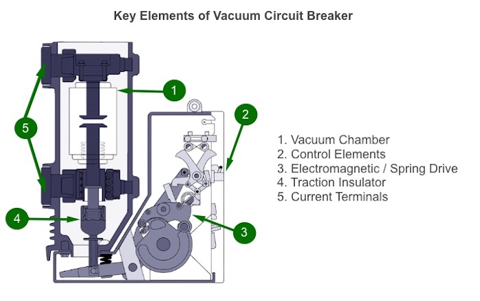
Vacuum Interrupter Chamber (Bottle)
The vacuum arc quenching chamber consists of insulators, a movable and a fixed contact, o-rings and a bellows.
The vacuum interrupter chamber is the heart of the vacuum circuit breaker. It must be able to switch rated currents thousands of times and handle short-circuit currents dozens of times. In the open state, the chamber must be able to withstand the voltages applied to it. Vacuum Interrupter bottle must retain its vacuum and all of its functionality for decades without the need for maintenance.
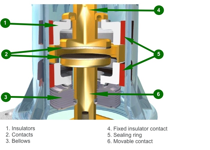
All materials used in chamber should be degassed, otherwise during the operation of the chamber there will be a gradual increase in pressure due to the release of gases dissolved in the structural elements, leading to the loss of electrical strength and failure of chamber. Lack of technologies for deep purification of materials has long held back the development of vacuum arc technology.
How Does a Vacuum Interruptor Work?
The physics of the arc quenching chamber process is based on the high strength and arc quenching capability of the deep vacuum medium. The free passage of electrons is several times greater than the distance between VCB contacts and can reach hundreds of meters. The vacuum volume between the contacts cannot serve as a source of charged particles due to the absence of shock ionization.
What happens when the contacts open? Along with the process of passing the first current in the arc through zero, the electrical strength of the intercontact volume in a vacuum rises rapidly. This helps to restore the insulation and prevent the arc from burning. Proper current switching in a vacuum environment is achieved when the arc energy is low.
Contacts of Vacuum Interrupter Bottle
The contacts are very important in any mechanical switching device (circuit breaker), since they have the dual function of carrying current (often quite large) when the circuit breaker is on and withstanding the applied voltage when it is off. However, in a vacuum circuit breaker, they also provide an environment for arcing during the transition of the circuit breaker from the on to the off state. Thus, it is possible to formulate the necessary qualities that must be inherent in the contact material for vacuum interrupters:
- Good electrical conductivity to minimize electrical losses during current flow
- Good thermal conductivity to improve the removal of heat generated when current flows through the contacts (since vacuum has excellent thermal insulation properties)
- Good dielectric properties to ensure the electrical strength of the vacuum gap when the circuit breaker is off
- Good breaking capacity when switching currents of any level
- The ability to resist the occurrence of welds or easily break the formed weld points
- Mechanical stability when operating under conditions of significant cyclic shock loads
- Good workability and manufacturability
- The ability to maintain a stable arc at low currents to prevent switching overvoltages (low cut-off currents).
Resistance of vacuum arc chamber contacts to welding is one of its most important qualities. It is known that metal parts pressed against each other in a vacuum environment are susceptible to cold welding, because no oxides that prevent this process can form on their surfaces. In addition, the contacts are exposed to through short-circuit currents, melting the metal in some points of the surface due to the high current density in them, resulting in the formation of welding areas in these points.
This problem was one of the reasons that delayed the development of vacuum switching technology for more than twenty years. Currently, the problem of contact welding has been overcome by the simultaneous introduction of several technical solutions in the designs of the vacuum chamber and vacuum circuit breaker.
The contact material has a very large influence on the characteristics of a vacuum circuit breaker. The metal alloys used must be mechanically strong, as well as erosion-resistant and weld-resistant.
The use of copper contacts reduces the effect of overloading by more than half. However, copper contacts are prone to wear and welding in a vacuum environment.
The metals molybdenum and antimony are added to the contact surface to avoid welding and increased wear. Molybdenum is an arc resistant metal, and antimony can create high vapor pressure.
Previously used tungsten did not allow to achieve optimum electrical and thermal conductivity. The use of copper alloy with the addition of boron, bismuth and iron instead of tungsten has improved these indicators. It is possible to avoid contact oxidation in a deep vacuum environment, where there is no oxygen gas, which is the main oxidizing agent of contacts in the atmospheric state. The absence of oxidation and increased wear resistance of contacts is, without any correlation, a direct positive correlation. However, vacuum, in contrast to the atmospheric environment, reduces the cooling efficiency of the contact group. A correction of the heat exchange processes is achieved by increasing the contact bar area in combination with innovative solutions for vacuum chambers.
The speed of operation of the vacuum chambers was increased tenfold in contrast to oil circuit breakers through the use of an end contact system. The contact travel range was reduced to 20 mm, which directly affected the speed of the entire switching module.
There is positive experience with the use of cermet materials in contact groups. Special metal-ceramic contact pads were developed that, on the one hand, have a very high resistance to weld formation and, on the other hand, have a granular structure so that the already formed welds could be easily broken by the switch actuator. An example of such a material is the copper-chromium composition that is now widely used around the world. In addition, actuators have been developed that provide a fairly significant (2000-3000 N) additional contact compression force to prevent electrodynamic rejection of the contacts and reduce their transient resistance. Finally, the actuators have been designed so that the resulting breaking forces at trip of the circuit breaker were sufficient to overcome possible contact welding and opening of the contacts.
Actuator Mechanism Types
An important element of a vacuum circuit breaker that affects its reliability is the actuator designed to control the movement of the power contacts and lock them in the on and off positions. The type of actuator can be electromagnetic, spring-motor, electromagnetic actuator.
Spring Actuators
Spring actuators have the following advantages:
- Low current consumption both when switching on and when switching off;
- AC and DC operating current applications (motors and AC/DC solenoids);
- on/off capability without operating current;
- Relatively low weight;
- Small dimensions;
- Absence of vibration and noise when switching on.
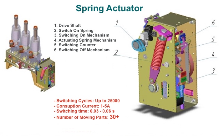
The disadvantages of this type of actuator are:
- operation in normalized recloser cycles, determined by the rate of spring engagement;
- more complicated kinematic scheme in comparison with the electromagnetic actuator
Electromagnetic actuators
Electromagnetic actuators have the following advantages:
- Simple design and minimum number of assemblies;
- Possibility of operation in any reclosure cycles (limitation only in heating of the switching on solenoid).
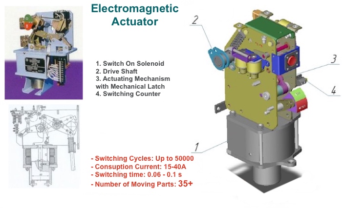
The disadvantages of this type of actuators are:
- High current consumption when switching on (the use of a contactor in the switching circuit), the need for a powerful power supply;
- High cross-section of power cables;
- No possibility of control without operating current; manual override is forbidden;
- For AC applications, a rectifier must be installed for - high current;
- High weight;
- Large dimensions;
- High vibration and noise when switching on.
Actuator with Magnetic Latch
The introduction of the electromagnetic actuator has greatly increased the speed of the switch. The electromagnetic actuator is based on the ability to magnetize and demagnetize an armature made of a magnetically hard material. After switching on, a current pulse passes through the coil which magnetizes the armature. The armature is set in motion by magnetic force, driving the moving electrode, compressing the trip spring. Due to the magnetism of the armature being saved, the switch remains on indefinitely without any additional current flowing through the coil. After tripping, a current pulse of the opposite polarity is used and the armature is demagnetized, the actuator is released from the magnetic latch and the contacts are opened by the trip spring.
The "magnetic latch" actuator was first used by Tavrida Electric and has the following advantages:
- Simple design and minimal number of components;
- Possibility of working in any recloser cycles;
- Low weight and dimensions;
- Possibility of operation in any spatial position;
- Maintenance free;
- Absence of vibration and noise during operation.
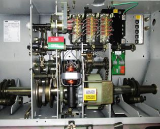 |
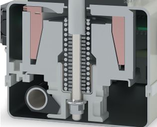 |
|---|---|
| Spring charge motor mechanism | Linear motor |
| Many prone to failure rotating parts | No rotating parts |
| Slow opening /closing time | Fast opening / closing time |
| Need for several auxiliary supply circuits | Only one auxiliary supply circuit to control module |
| High auxiliary power consumption during operation | Low auxiliary power consumption during operation |
| Need for additional TCS relay for monitoring | Built in self-supervision system |
| Extensive maintenance requirements | No maintenance requirements |
| Obsolete technology! | Superior technology! |
Advantages and disadvantages of vacuum circuit breakers over other types: SF-6 (gas), Oil and Electromagnetic
Unlike switches with spring-motor drive, the modern design of vacuum switches provides the simplest kinematic scheme of contact system movement and almost complete absence of rotating and rubbing parts.
Advantages
- simple design
- fire safety
- high reliability
- high performance
- high switching life
- no harmful emissions
- quiet operation
- small size and weight
- high breaking capacity
- maintenance free
There is absolutely no need for current, medium and overhaul repairs, as well as any kind of maintenance.
| Type of CB | Electromagnetic | Oil | SF-6 | Vacuum |
|---|---|---|---|---|
| Modern technical level | No | No | Yes / No | Yes |
| Reliability / Durability | No / No | No / No | Yes / No | Yes |
| Need to control the environment / Operating contacts | No / Yes | Yes / Yes | Yes / No | No / No |
| Cost of ownership, relative units | - | 1,5 - 1,7 | 3-5 | 1 |
| Weight, kg | Over 400 | From 140 | From 110 | From 35 |
Disadvantages
- Limited range of rated operational voltages (up to 110 kV)
- Possibility of overvoltages during switching
Optimal VCB Uses for Medium Voltage (MV)
For vacuum chambers there is a natural limit to the withstand voltage. For this reason, vacuum switching technology has a technological niche of applicability in voltage classes from 400 V to 38 kV inclusive, and other technologies in these classes are largely superseded. For applications in higher voltage classes, such as load-break switches up to 230 kV, the vacuum chambers have to be connected in series. However, when it comes to vacuum circuit breakers capable of switching fault currents at high voltages, it is hardly possible to find any such offerings on the breaker market today. For high-voltage networks, gas-insulated circuit breakers are used.
VCB Applications for High Voltage (HV)
Nowadays, highly reliable, fast-acting VCB capable of breaking currents of up to 100 kA and operating at voltages of up to 84 kV are commercially available. The operating voltage is limited by the need to connect a number of chambers in series. For high voltage for instance, 220 kV circuit breakers require four 84 kV chambers. There are other difficulties in creating a multi-break vacuum circuit breaker.