Capacitor Bank Switching With Tavrida Vacuum Circuit Breakers

As many of our customers have noticed, Tavrida vacuum circuit breakers offer extremely long mechanical and electrical life – the amount of operations a contactor can offer, while providing complete circuit breaker functionality. We propose to consider the application of Tavrida VCB for capacitor bank switching transients.
Table of Contents- Introdution
- Capacitor Bank Switching Problem - Voltage Synchronization
- Reducing Vacuum Interrupter Dielectric Strength
- Vacuum Gap Withstand Ability
- Cleaner Vacuum Gap
- Conclusion of Capacitor Switching Transients
- Article Source
This combination of parameters is quite unique in the industry, which results in a lot of our partners’ inquiries willing to benefit from this in their applications.
It is no exaggeration to say that most of the inquiries refer to power factor correction or switched capacitor filter. And the reason is very simple – such load is switched at least three times a day – to compensate for grid losses or harmonic detorsion caused by daily consumption fluctuations. Massive increase of non-fossil generators makes operations number for such installations even larger – switching is necessary for power production changes during the day.
Put together all above and the breaker shall perform at least a thousand operations every year. Obviously, none of the users is willing to perform inspections on such breaker every year and moreover service is somehow. That’s where Tavrida can provide advantage.
However, probably everybody heard that switching load like capacitors, shunt reactors or harmonic filters has some peculiarities. Below we try to describe those very briefly and provide you with guides on where to watch and how to get all breaker benefits you need when using it for capacitive power compensation and harmonic filters switching.
Capacitor Bank Switching Problem - Voltage Synchronization
Every engineer knows that circuit breaker interrupts alternating current at its zero. So after a bank capacitor is tripped, it is fully charged to the network rated voltage amplitude. This means that in half cycle after the trip, vacuum interrupter receives grid voltage on one side and opposite voltage on the other. Double voltage across the interrupter!
What would happen if the vacuum gap (occasionally) breaks down in this very moment? A transient process would start recharging the capacitor to the grid voltage, however, with an overshoot effect of an oscillation process. When the capacitor current is zero again, the breaker will easily interrupt it (remember the interrupter is open). However, this time capacitor will be recharged to 3x rated network voltage amplitude. Now we get 4x amplitude voltage across vacuum interrupter in half a period. In case breakdown occurs again, we get 5x on the capacitor, etc…For sure some piece of equipment connected to such network will be the first to fail under these conditions.
Though, at first glance, why would the first breakdown occur? Even double voltage across the vacuum gap is still too small to cause any problems for vacuum circuit breaker designed to withstand power frequency voltage across itself. For instance, 13.8 kV grounded network with 11.3kV phase-to ground amplitude, even doubled, provides 22.6kV across gap. A gap which is designed to withstand 54kV peak ( based on 38kV PFWV RMS). This looks like more than double margin, so why would such voltage be a problem?
Reducing Vacuum Interrupter Dielectric Strength
To make a very long story (which numerous researchers, including our R&D department have thoroughly examined) very short, vacuum circuit breaker may break down when switching capacitive load because there is some “rubbish” in the vacuum gap and sharp roughness on contact surfaces after trip caused by prior capacitor energization. Why? Because compared to any other load type, capacitor current raises very fast after initial breakdown of narrowing vacuum interrupter gap in the process of closing. So fast that current reaches significant values or even maximum while vacuum interrupter is still not mechanically closed. This current would heat a very small portion of contact surface material and melt it. Immediately after mechanical closing, this material would freeze.

Using Tavrida VCB for Capacitors
Afterwards, when breaker is required to trip, this melted portion cracks in numerous particles of different sizes, which fill the gap and, along with contact roughness in the point of melting, reduce vacuum interrupter dielectric strength - exactly the dielectric strength, which is necessary to withstand the increased voltage.
As one may have guessed already, there are two ways to solve the problem:
- Increase contact gap to deal with voltage regardless of any particles in it
- Decrease the amount of particles which, in their turn, decrease the gap breakdown voltage
Vacuum Gap Withstand Ability
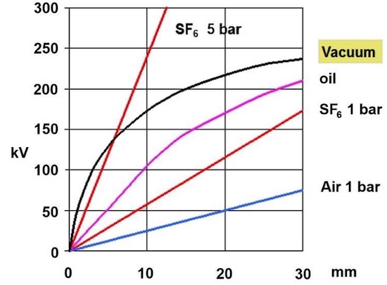
How can vacuum gap withstand ability be increased? The obvious way is to increase its size, but it does not look optimal. Just look at the chart below [1] showing vacuum interrupter dielectric strength depending on its gap size. Breakdown voltage increases gradually, however, the more the gap, the less the increase.
NB! Please don’t try to achieve 160kV withstand in an industrial vacuum interrupter on 5mm gap.
The chart below is applicable for ideally treated surfaces in lab conditions, which you can check in the original article. However, the effect itself is clear.

Dependency graph vacuum interrupter dielectric strength on its gap size
Imagine you choose between taking two consequent gaps of 5mm or one of 10mm. First option will provide almost double withstand ability!
Cleaner Vacuum Gap
Clean vacuum gap at voltage peak is provided by less melted spot upon its prior closing. Though we cannot directly define the size of such spot, there are various concepts of the electrical criteria to assess circuit breaker application from this point of view. In Tavrida, we use a simple, but field proven one – peak value of capacitor energization current.
In its turn, peak capacitor energization current is influenced by:
- Capacitor bank size - the larger it is, the higher the peak energization current.
- Series inductance. The larger the inductance between the power source and the capacitor, the less the peak energization current. Any inductance between power source and the capacitor contributes to this effect - busbars, overhead line, transformer, dedicated inductance, etc.
To estimate if the breaker can be used for capacitor switching in particular point on the network, engineer shall know the safe value of peak energization current for particular vacuum interrupter. In Tavrida we ran numerous surveys that defined this value. Actual peak energization current shall be calculated for the application and compared to the safe one for the breaker.
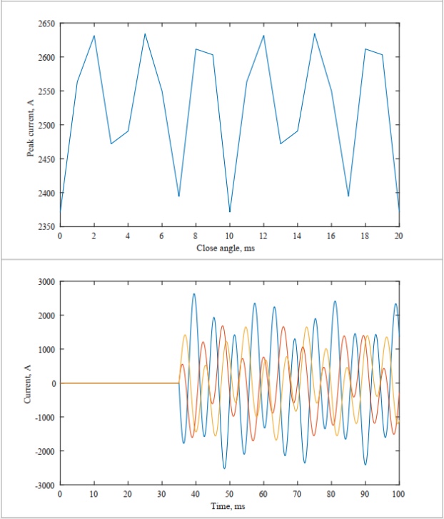
To assist our customers with proper vacuum circuit breaker selection, we perform surveys on breaker applicability on request. To execute the survey, we consider a single line diagram of the complete electrical installation. Not only the network portion between the source and the capacitor matters, but also the neighboring elements, like parallel connected capacitors or large network segments, may influence the result. We run the peak energization current calculation for various breaker closing phase angles to define worst case scenario. One of the examples of peak energization current calculation is shown in the picture below.

Discharged Bank Switching. Depending peak voltage on close angle
To summarize it, we would be happy if it would, but, unfortunately, capacitor rated current alone does not define vacuum circuit breaker applicability. It can be a huge 1000A rated bank, however damped with a proper series inductance, which would produce energization current only a little higher than the bank rated current, and the breaker would work fine. On the other hand, a relatively small bank without any damping, or, even worse, connected parallel to a large pre-charged capacitance, may cause breaker restrikes and system failure.
Conclusion of Capacitor Switching Transients
Applying vacuum circuit breakers for capacitive and harmonic filters switching requires expertise of the breaker manufacturer, who shall know the critical value of capacitor peak energization current and vacuum interrupter withstand ability parameters. This is required in order to offer suitable circuit breaker type and assess its application considering capacitor maximum peak energization current which may occur in the installation.
Article Source
- CIGRE WG A3.27, “The Impact of the Application of Vacuum Switchgear at Transmission Voltages”, CIGRE Technical Brochure 589, p. 17, 2014z
