Withdrawable AIS panels 12 - 24 kV
Tavrida Electric presents Air-insulated Switchgear
As the inventor of a revolutionarily new design of VCB with magnetic actuators in the 1980s, it was logical for Tavrida Electric to bring into the market another innovative product that beats its peers in terms of public and operator safety, style, reliability, performance and environmental sustainability. Based on vacuum switching technology, air insulation, digital protection and arc-flash relays, air-insulated switchgear inherently saves the environment as it is an SF6-free switchgear.
Tavrida Electric air-insulated switchgear of MILE series, which comprises a complete range of 12, 17.5 and 24kV voltage classes, is intended for operation in diverse industries.
MILE switchgear
Compliance with IEC 62271-200 to perform safer.
MILE is designed to meet the LSC2B-PM AFLR 31,5kA 1s classification as per IEC 62271-200.The design is fully type tested to IEC 62271-200. The following type tests have been successfully passed:
- Short time and peak withstand current on primary circuits
- Short time and peak withstand current on earthing circuits
- Temperature rise and main circuit impedance
- Dielectric test on main and auxiliary circuits
- Making and breaking capacity of the circuit breaker within the panel
- Earthing switch making capacity
- Mechanical operations
- IP code
- Internal arc fault (IAC classified: AFLR, 31.5kA/1s)
Exceptional safety
In addition to IEC 62271-200 requirements, the application of TAVRIDA ELECTRIC VCB with MAGNETIC ACTUATORS in MILE provides unique and unrivalled safety features such as remote and safe manual closing of VCB with a palm-held manual generator and the fastest arc fault interruption in less than one cycle.High operational reliability
- The robust enclosure, made of 2mm corrosive resistant hot-dip galvanized metal sheets with reinforced doors and a safety labyrinth allows fast and simple erection even on an uneven floor.
- A rivet nut design provides not only the rigidness of construction but also an opportunity to replace metal parts on site without the use of special tools.
- An emergency trip push-button is located in the center of the panel. It has a striking, protruding design protected against accidental operation. The trip button can be quickly spotted in an emergency.
- Large and clearly visible mechanical position indicators located in view of an operator allows him to positively identify the operating status of the draw-out unit, VCB and earthing switch. Each mechanical indicator abruptly changes its status so that it exactly corresponds to the status of the switching device. Mechanical position indicators are duplicated by electrical auxiliary contacts to provide electrical signals into secondary circuits.
- Lockable access to the VCB racking in/out mechanism by a metallic shutter prevents unauthorized operations and interlocks the VCB in the trip position prior to racking a draw-out unit.
- An LV plug interlock visually prompts an operator to connect the draw-out unit to secondary circuits before the compartment door is closed.
- Refined accessories, such as door hinges, handlebars, locks and electrical indicators and buttons withstand thousands of operations and guarantee the appearance of a beautifully crafted product.
- Minimum service checks on site. MILE is designed for a service life of at least 30 years. The VCB, earthing switch and cast resin insulation technology is considered virtually maintenance free, so the maintenance requirements are only related to periodical checks to make sure that the system operates correctly.
Greater application versatility
- The design of 12, 17,5 and 24kV panels is unified.
- Cassette and truck versions are available.
- Front or Front and Rear accessibility to the cable compartment
- Two sets of CTs and VT cassette placed in VCB or cable compartments.
- Panel width can be 600, 750 or 1000mm.
-
ONE CYCLE INTERRUPTION
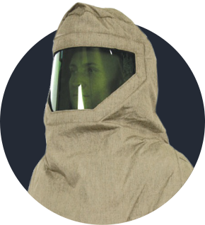
Electrical workers have been chosen as the third most dangerous occupation according to recent OSHA (the Occupational Safety and Health Administration, USA) statistics. In the USA alone, there are 10 OSHA ‐ reportable arc‐flash incidents involving more than one fatality every day. Studies indicate that up to 80% of all Electrical Worker injuries are not due to shock (passage of electrical current through the body) but due to external burn injuries created by the intense and radiant heat energy of an electrical arc explosion. There is a great deal that can be done to prevent an Arc Flash explosion and to protect personnel if they are exposed to an Arc Flash.
-
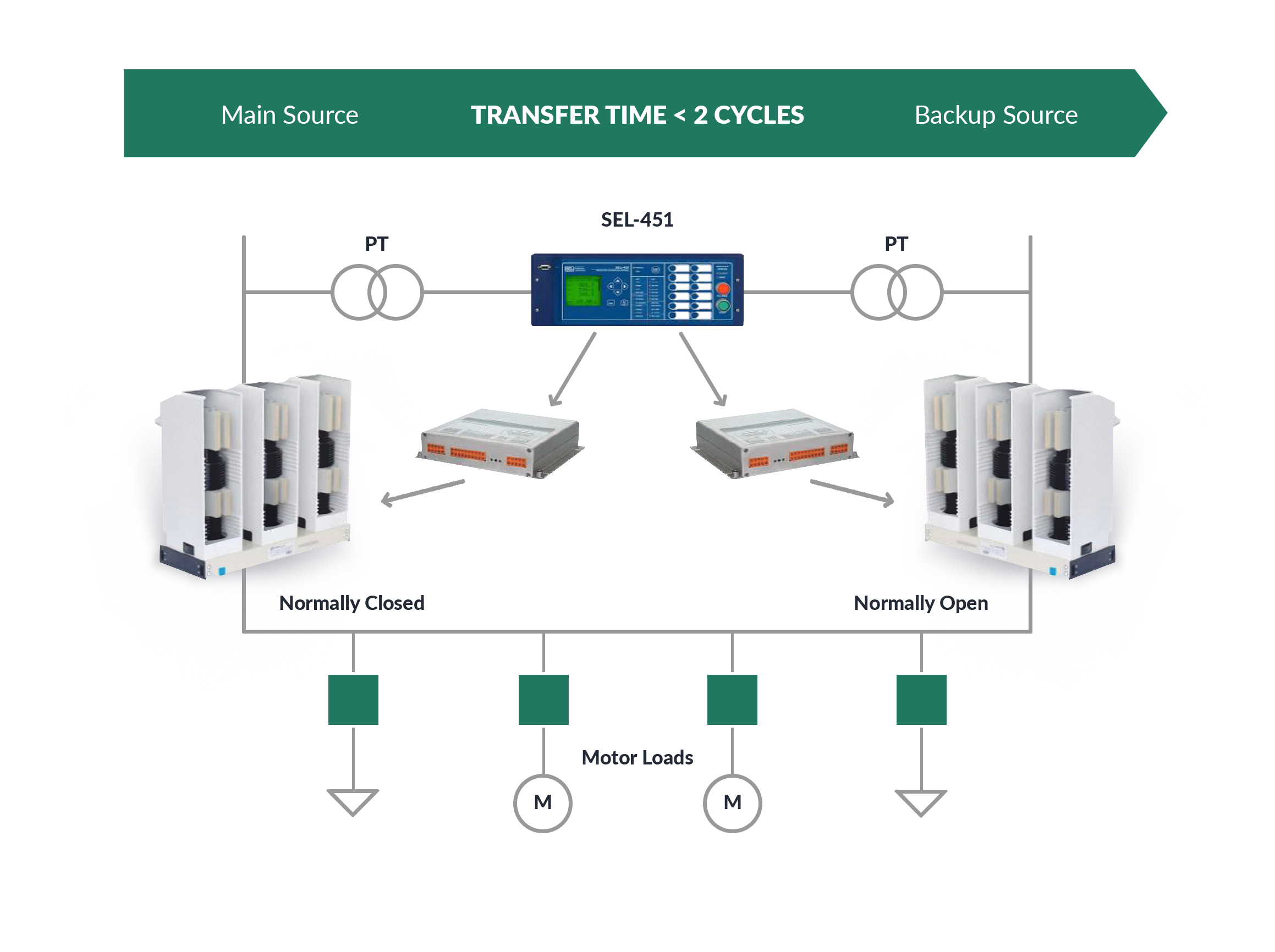
FAST TRANSFER SWITCH
In order to ensure continuity of power supply, two independent incoming feeders are usually provided to switch the load over to a healthy source when required. Conventional Transfer Systems based on an undervoltage protection have to be coordinated with protection relays of adjacent feeders and the reclosing relay of an upstream breaker. This results in a time delay of as long as several seconds.
Field-proven design
MILE has a typified design so that the arrangement of equipment and instruments in the panel represents the mainstream concept of switchgear specified by most customers worldwide. In addition to draw-out units at a central location and make-type earthing switches, the design is considerably augmented to provide exceptional safety, absolute reliability and top performance.
MILE is created for straightforward manufacturing. No turning, grinding or cleansing is necessary. No jigs or welding processes are required for assembly. The enclosure is made of corrosive resistant hot-dip galvanized metal sheets. Its design allows fast assembly with rivets and screws only.

-
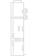
LV COMPARTMENT The compartment is of a detachable design for easy and convenient handling during transportation and erection on site. It is segregated with earthed metal partitions and has ample space for multi-functional protection relays, energy meters, lighting, heating and many other devices.
More -
VCB COMPARTMENT Fully segregated by earthed metal partitions and having its own pressure relief channel, the VCB compartment houses the bushing insulators containing fixed contacts for the connection of the circuit breaker to the busbars and the cable compartment. The bushings are covered by automatic metallic shutters. All safety interlocking mechanisms required for safe and reliable operations of the VCB, an emergency trip push-button, two inspection windows for mechanical position indication: one for VCB and the other for draw-out unit mechanisms; are fitted into the compartment. The VCB is mechanically and electrically interlocked with the compartment door so that the door cannot be opened until the VCB is turned off and racked out to the test position. For extra safety, the tool orifice to the racking in/out mechanism is equipped with a shutter operated by a keylock.
More -
AUTOMATIC SHUTTERS Individually operated earthed metallic shutters are automatically driven during the movement of the VCB from the test to the service position and vice versa. The busbar and cable shutters can be separately padlocked in the open position to prevent accidental contact with any live parts.
More -
BUSBAR COMPARTMENT The busbar system is made of electrolytic copper and totally enclosed in its own earthed metal compartment with a pressure relief flap on the top. The busbars are connected to the fixed contacts of the upper bushing insulators by means of branch connections. Optionally, the busbars and the branch connections can be completely insulated. The busbar compartment of each panel is segregated from the adjacent busbar compartments with through insulators.
More -
GAS EXHAUST DUCT The gas exhaust duct accommodates all three pressure relief flaps and is mounted on the top of each panel. It runs along the whole length of the switchboard. The pressure generated by the internal arc makes a pressure relief flap open thus allowing hot gases to run into a special chimney to be evacuated to dedicated areas.
More -
CURRENT TRANSFORMERS To facilitate maintenance, cast resin CTs are fitted onto a pivoting plate. The fixing points of the plate can receive a wide range of CTs of different brands. Two sets of CTs can be installed on a panel for distance or differential protection.
More -
VOLTAGE TRANSFORMERS VTs with replaceable primary fuses and a striker system can be mounted on central or lower draw-out units. The striker system is intended for sending a signal about a blown fuse into the SCADA system. Optionally, fixed or top installations of VTs are available.
More -
EARTHING SWITCH The make-type ES is equipped with a mechanical position indicator that can be viewed through the inspection window on the cable compartment door. An additional mechanical position indicator is located in the ES operating mechanism. The ES can be operated manually from the front of the panel or by an electrical motor via SCADA. The ES is mechanically and electrically interconnected with the VCB and the cable compartment door to provide exceptional operator safety.
More -
CABLE TERMINATIONS Single and three-core cables up to a maximum of 7 per phase and up to 4 cables when a VT draw-out unit is installed, can be used depending on the rated voltages, panel dimensions and cable cross section. Cables are terminated with compression lugs onto copper tails and fixed by cable glands.
More -
EARTHING BAR Made of 10x30mm electrolytic copper, the earthing bar runs along all adjacent panels and connects to the main earthing bar of the substation. All current carrying parts are interconnected with each other for equipotential bonding to guarantee personal safety against electrical shock.
More